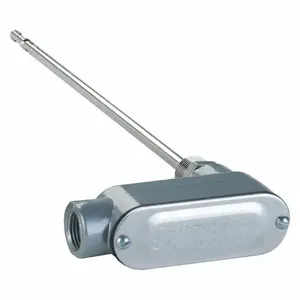
Dwyer Instruments 641-12-LED air velocity transmitter is ideal for airflow monitoring in air control, HVAC, exhaust stack, drying, fan supply and ventilation operations. This test device may be utilised with a range of flow rates & temperatures and offer velocity data. It helps in cleaning compatible, non-combustible gases and air.
Features:
- Dwyer Instruments 641-12-LED air velocity transmitter has a digital filter to offer signal damping.
- The compact, NEMA 4X enclosure ensures high durability.
- It allows 16 field-selectable ranges for user convenience in several airflow applications.
- This unit comes with a heated mass flow sensor for accurate velocity measurements at different temperatures & flow rates.
- It is configured with a simple push-button set-up for easy calibration & installation as well as minimising system complexity.
Compatible Accessories:
- Dwyer Instruments Optional LEDs: They offer a full, affordable solution for the local indication of air flow.
Standards and Approvals:
Frequently Asked Questions:
Q. How to select a suitable location to install this transmitter?
A.
- To attach the enclosure, choose a site where temperature ranges from 32 to 140 degrees Fahrenheit.
- As long as the entire loop resistance is under 600 ohms, the transmitter can be placed at any distance from the receiver.
- The probe should be placed in an area with conditions that are typical of the entire environment being observed.
- Avoid areas with turbulence, stagnation or quickly changing temperatures or velocities because these factors could impact the measurements.
- In turbulent situations, the filter setting can be used to average velocity values.
Q. What should be the position of the transmitter while installation?
A. The transmitter is not position-sensitive and can be installed in any orientation.
Q. How to install air velocity transmitters?
A.
- A 1/2 inch NPT male integral connection enables the direct installation of pipe fittings or a pipe flange.
- A 5/16 inch compression fitting can also be used to install it.
- The calibrated airflow's direction is shown by arrows on the hex flats at the base of the probe.
- Put these arrows in the process air's direction.
- For easier attachment, the casing may spin apart from the probe.


