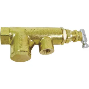
Conrader RCL-S-HU-115-130 unloader pilot valve is ideal for operating connected devices like shuttle valves, normally open / close valves, drain / discharge valves, unloader valves & throttle controls for controlling engine speeds in compressed air systems. It is also used for regulating the device output by actuating the unloader mechanism of the intake valve or the discharge mechanism of the compressor when there is a greater compressed air supply than the demand.
Features:
- Conrader RCL-S-HU-115-130 unloader pilot valve has a brass body with stainless steel pilot valve ball for corrosion resistance.
- The unload set pressure (cut-out) in this valve refers to the maximum pressure setting at which the valve operates the intake unloaders or discharge mechanism for venting the compressor delivery into the atmosphere.
- The load set pressure (cut-in) refers to the minimum pressure setting at which the unloader pilot valve actuates the compressor to restart producing compressed air.
- The differential refers to the pressure range between the load & unload pressures.
- It has two adjustment screws & two lock nuts of pressure & differencial types to set the load and unload pressure.
- This pilot valve has an adjustable pressure range of 115 to 130 psi.
- It comes with a removable side-mounted strainer to prevent the entry of contaminants into the connected devices.
Compatible Accessories:
- Dual Control Lockouts: The manual hand unloader lever of this unloader pilot valve can be replaced with a dual control lockout for switching between start / stop and continuous operation on electric motor compressors.
Frequently Asked Questions:
Q. What is the operating temperature of this Conrader RCL-S-HU-115-130 unloader pilot valve?
A. This valve operates at temperatures ranging from -15 to 400 degrees F.
Q. What are the connections available in this Conrader RCL-S-HU-115-130 unloader pilot valve?
A. It has a 3/8 inch FNPT inlet and a 1/4 inch FNPT outlet.
Q. How to adjust this Conrader RCL-S-HU-115-130 unloader pilot valve?
A.
- Differential adjustment screw & locknut is below the pressure adjustment screw & locknut. Users should remember their location before adjustment.
- Drain the system air from the system and inspect the safety device. Loosen both the differential & pressure adjustment locknuts fully and then gently turn the differential screw in the clockwise direction till it stops.
- Remove the pressure adjustment screw from the valve body and then reinstall it by turning it two full turns.
- Restart the compressor and then increase the pressure to reach the desired load pressure. Turn off the compressor.
- Back off the differential screw by 1/3 of a counterclockwise turn to allow actuating of unloading devices as in normal operation. Tighten the differential locknut.
- After the desired load pressure is attained, turn the pressure adjustment screw slowly in the clockwise direction. As you are turning the valve, wait for the valve to load. It will exhaust air from the top of the valve body and make a hissing noise. Once air gets exhausted from the top of the valve body by making a hissing noise, tighten the pressure adjustment locknut.


